Choose I about the axis of the bending moment. The depth perpendicular to that axis is the dimension cubed in bh³/12.
Match the force, bending moment, and section axis
Imagine looking at the cut end of a straight beam. Its length runs into the page. A downward transverse force produces bending about a horizontal axis in the cross section. In this guide that axis is named u; the vertical section direction is v.
For this symmetric rectangle, bending without an axial force has a centroidal neutral axis. Use the second moment of area about u when estimating vertical deflection. For a sideways transverse load, use the corresponding vertical-axis property instead.
Manufacturer labels such as x–x, y–y, major, and minor are useful only alongside the section sketch. Axis names are not universal. Confirm that the published axis represents the beam's actual installed orientation.
Why the dimension perpendicular to the axis is cubed
The geometric definition is Iu = ∫Av² dA: each area element is weighted by the square of its distance from the axis. For a solid rectangle with width b parallel to u and depth h perpendicular to it, Iu = bh³/12. MIT Lecture 4 gives the area integral and rectangle relationship.
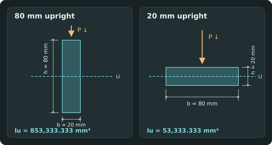
Consider a solid 20 × 80 mm section. Turning it through 90° does not change its area, material, or mass, but swaps which dimension lies perpendicular to the horizontal bending axis.
| Installed orientation | b (mm) | h (mm) | Iu (mm⁴) | Iu (cm⁴) |
|---|---|---|---|---|
| 80 mm upright | 20 | 80 | 853,333.333 | 85.333333 |
| 20 mm upright | 80 | 20 | 53,333.333 | 5.333333 |
The upright orientation has 16 times the second moment of area about the relevant axis: Iupright/Iflat = (80/20)² = 16. With E unchanged, its bending rigidity EI is also 16 times larger.
Do not always cube the larger dimension. Cube the dimension perpendicular to the axis of the bending moment, even when that is the smaller dimension in the installed orientation.
Compare two independently checked deflections
Use an ideal simply supported beam with span 2 m and a central point load of 1 kN. Assume a constant Young's modulus E = 200 GPa, linear elastic behaviour, small deflections, and no added self-weight. Only the section orientation changes.
For this load case, δmax = PL³/(48EI), as developed in MIT Lecture 5. In N and mm, P = 1,000 N, L = 2,000 mm, and E = 200,000 N/mm². Keeping this unit set consistent gives deflection directly in mm.
| Orientation | I to enter (cm⁴) | Maximum deflection (mm) |
|---|---|---|
| 80 mm upright | 85.333333 | ≈ 0.976562 |
| 20 mm upright | 5.333333 | ≈ 15.625000 |
The flat orientation deflects 16 times as much. In either orientation, the ideal vertical support reaction is 0.5 kN at each end and the maximum bending moment is 0.5 kN·m. Those statics values are unchanged; the section's resistance to bending changes.
The separate numerical check integrated the actual-load moment multiplied by a unit-load moment over the span, divided by EI. This virtual-work check agrees with the closed-form result and is based on MIT's energy-method treatment.
Read the property and its units before copying a table value
- Second moment of area I
- Used for bending stiffness and deflection; units are length⁴, such as mm⁴, cm⁴, m⁴, or in⁴.
- Section modulus
- A different property used in bending-stress calculations; units are length³. It must not be pasted into an I field.
- Mass moment of inertia
- A rotational dynamics property with units such as kg·m²; it is not the area property used here.
- Polar area moment
- Another length⁴ property associated with torsion in particular models; matching units alone does not make it the correct bending I.
Fourth-power unit conversion matters: 1 cm⁴ = 10,000 mm⁴ and 1 m⁴ = 10¹² mm⁴. Select the calculator's I unit to match the source value. A cm⁴ value labelled as mm⁴ makes the stated stiffness 10,000 times too small.
The rectangle formula applies to a solid rectangle. For hollow or rolled sections, use the correct geometry or a manufacturer section table that includes its dimensions and radii. Built-up sections need a centroid calculation and, where appropriate, the parallel-axis relation I = Icentroid + Ad². Do not use a surface-axis value in a centroidal bending model.
Unsymmetric sections, combined bending about two axes, torsion, significant shear deformation, or instability need a more complete analysis. A favourable deflection result alone does not establish adequate strength or stability.
Inputs to use in the Beam Deflection Calculator
- Select Metric → Simply supported, center point load → Structural steel.
- Enter span 2 m and point load 1 kN. The example assumes E = 200 GPa.
- Select cm⁴ for the second-moment unit.
- Enter I = 85.333333 cm⁴ for the 80 mm upright orientation; then compare I = 5.333333 cm⁴ for the flat orientation.
The table uses the unrounded rectangle properties. Copying the rounded cm⁴ inputs into the calculator gives approximately 0.976563 mm and 15.625001 mm; the last-digit differences are rounding effects. Include self-weight in the entered load when your application requires it; the example above compares only the applied point load.
Compare beam deflectionsSources and verification
- MIT Structural Mechanics, Lecture 4 — Constitutive Equations
Equations 4.27–4.29: bending rigidity EI, the area integral for I, and the rectangle formula. - MIT Structural Mechanics, Lecture 5 — Beam Deflections
Ideal beam boundary conditions and the central point-load deflection solution. - MIT Structural Mechanics, Lecture 8 — Energy Methods
Virtual-work basis for the separate numerical deflection checks.
Section properties were independently checked by integrating the squared distance over each rectangular area. Deflections were checked by virtual work and compared with the calculator using both full-precision and the stated rounded cm⁴ inputs. The examples are ideal model calculations, not measurements of a tested beam.